The explained circuit in this article is probably the simplest and the cheapest, since it employs minimum number of components and the making of the circuit is very straightforward.
Generally SMPS topology involves some fixed standard stages and criteria. Thgey may be listed in the following manner:
The first stage which is the input stage incorporates an obvious mains rectifiers stage, followed a few important protection components.
The above protection components may be in the form of an MOV , or an NTC or both of these for suppressing high voltage transients.
The next stage involves a mosfet based IC in conjunction with the primary of a small transformer for generating the required oscillations.
The IC is normally a state-of -the-art chip having many in built features and abilities.
Further on the secondary of the transformer is clamped with the mosfet IC through a optocoupler which takes the responsibility of controlling the output voltage to a predetermined fixed level.
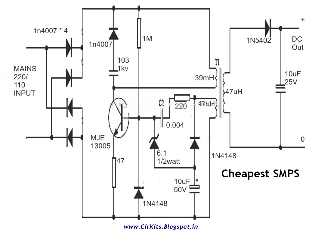
However the proposed circuit of a cheapest SMPS circuit is rather free from all these complications and employs a very simple configuration.
The input does not involve any protection, which is rather replaced with the snubber network around the transistor. Moreover the rugged MJE13055 is assumably strong enough to take on most the situations.
The two winding on the primary side are so arranged that on switch ON the circuit immediately starts oscillating at around 100 kHz.
The secondary winding typically decides the output voltage and here no optos or zeners are introduced for the sake of simplicity.
Having said that, the circuit may be considered quite crude and therefore in some way might be vulnerable at some point of time in the long run.
BRIEF SUMMARY:
The circuit was taken from some other website, I don't remember the exact location...roughly I can say the following:
1) Power will depend on the SWG of the sec winding, and the inductor size, but cannot exceed above 2amps.
2) I cannot say about the transformer winding detail, you may consult a professional coil maker. The inductor definitely needs to be done over E-type cores.
3) This circuit is crude, so cannot guarantee regarding output standards.
4) 13001, 13002 can be used.
5)1N5402 is more safe and a better option than two 1N4007s
plesae tell me working of this circuit.how transistor switching.
ReplyDeleteplease share transformer detils
ReplyDelete