 The ZN414 is a low cost, single-chip AM radio integrated circuit. Launched in 1972, the part was designed and supplied by Ferranti.
The ZN414 was popular amongst hobbyists as a fully working AM radio could be made with just a few external components, a crystal earpiece and a 1.5 V cell.
The manufacturing process for the ZN414 chip used a relatively new (for the time) technique known as Collector Diffusion Isolation (CDI). CDI was invented by engineers at Bell Telephone Laboratories and subsequently developed into a commercial process by Ferranti in the UK.
The original ZN41x family have equivalents to the original 3-pin ZN414 are available, with part codes of MK484, TA7642 and (mainly in India, the Far East & Australasia) YS414 and LMF501T. Note that on the YS414 part, pins 1 (output) and 3 (ground/earth) are transposed.
The original ZN41x family have equivalents to the original 3-pin ZN414 are available, with part codes of MK484, TA7642 and (mainly in India, the Far East & Australasia) YS414 and LMF501T. Note that on the YS414 part, pins 1 (output) and 3 (ground/earth) are transposed.
Notes:
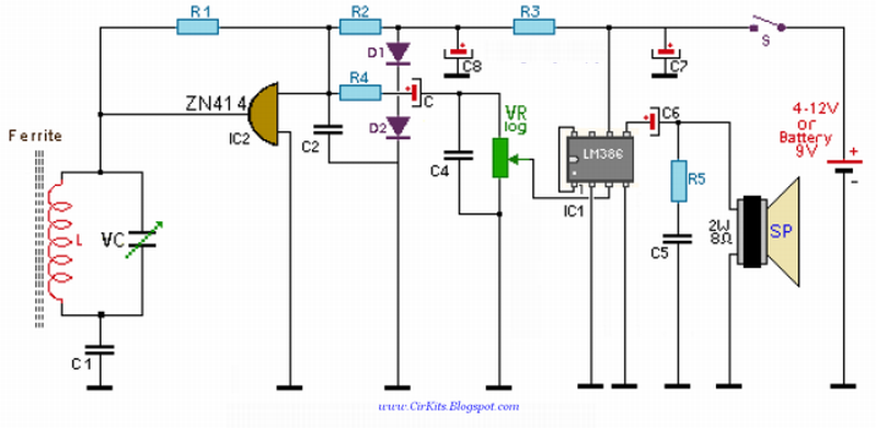
This is circuit design around the popular ZN414 I.C. this receiver covers the AM band from 550 - 1600 KHz values. For Long wave the coil needs to be changed. Use one from an old MW radio to save time.
This is circuit design around the popular ZN414 I.C. this receiver covers the AM band from 550 - 1600 KHz values. For Long wave the coil needs to be changed. Use one from an old MW radio to save time.
The ZN414 is a tuned radio frequency designed and incorporates several RF stages and an AM detector. It is easily overloaded and the operating voltage is critical to achieve good results.
The two 1N4148 diodes both supply 1,2Volt (0,6 Volt each).
The ZN414 is variable from 0 to 1.8volts DC. If you live in an area that is permeated with strong radio signals, then the voltage will need to be decreased. I found optimum performance with a supply of around 1.2 volts.
The audio amplifier is built around an LM386 op-amp. The voltage gain of the complete audio amplifier is around 15. The audio output of the complete receiver is really good and quite free from distortion.
The coil needs approximately 55 turns of 0.315 (30 SWG) of enameled copper wire on a 100 x 10mm ferrite rod. A process of trial and error will help you achieve the optimum number of windings.


Parts:
R1 = 100K
R2 = 1.5K
R3 = 1.5K
R4 = 470R
R5 = 10R
C1 = 0.01mF
C2 = 0.1mF
C3 = 1mF
C4 = 0.02mF
C5 = 0.05mF
C6 = 220mF
C7 = 220mF
C8 = 10mF
D1 = 1N4148
D2 = 1N4148
VR1 = 5K LOG
VC1 = 3 – 500pF variable
U1 = LM386
U2 = ZN414 or MK484 or TA7642 or LMF501T
L = (see text)
R1 = 100K
R2 = 1.5K
R3 = 1.5K
R4 = 470R
R5 = 10R
C1 = 0.01mF
C2 = 0.1mF
C3 = 1mF
C4 = 0.02mF
C5 = 0.05mF
C6 = 220mF
C7 = 220mF
C8 = 10mF
D1 = 1N4148
D2 = 1N4148
VR1 = 5K LOG
VC1 = 3 – 500pF variable
U1 = LM386
U2 = ZN414 or MK484 or TA7642 or LMF501T
L = (see text)
ReplyDeleteTHIS IS THE PICTURE BELONGS TO THE WEBSITE : http://elec-circuits.blogspot.com
A small mistake in the schematic. R1 should be connected to C1, not L1 otherwise R1 loads the tuning tank a little bit.
ReplyDelete